Configure System Galaxy Software
This topic covers configuring the System Galaxy software screens in order for the wireless readers to interoperate with System Galaxy.
Also See: The main SG Software User Guide describes the programming of cards, access rules, schedules, etc.
FEATURES
Configure Serial Channels (DSI Sections)
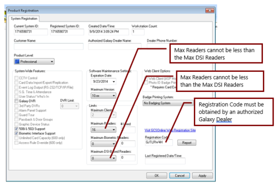
This information applies to registering "DSI-based" or Wireless Readers in System Galaxy product registration. You must have enough DSI-based readers registered or the system will not allow you to add the wireless reader.
Note: the term DSI-based refers to any reader that attaches to a DSI board (i.e., which wireless readers such as AD400, Salto, Assa
The DSI-based Reader Count will include any reader that is connected to a DSI Board. This number cannot exceed the Max Reader Count.
-
wireless readers (AD400, LE, NDE, etc.)
-
wired readers (AD300 model)
The Maximum Reader Count is the total number of readers that can be installed at the site, regardless of reader type (standard, biometric, wireless, etc.).
The [# Used] field will display the number of readers that are programmed into System Galaxy.
PREREQUISITES
-
The core GCS Services must be running.
-
You must sign-in as a master operator to register and program the system.
-
All settings in the Registration screen must match your purchase agreement.
-
If you need to install more readers than the purchase agreement shows, contact your Authorized Customer Service.
-
Open the Registration Screen: Configure > Options > Registration > System
-
Select the correct Product Level according to the purchased license agreement.
-
Configure the License, Customer and Dealer information.
-
Set the System-wide Options according to the purchased license agreement.
-
Set the Max Readers Count to match the purchase agreement. This count includes all readers, whether they are DSI-based or not.
-
Set the Max DSI-Based Readers count to match the purchase agreement. This count includes all reader that are connected to a DSI Board.
-
Complete the remaining options or settings according to customer agreement.
-
Enter the correct Registration Code.
-
Click Apply to save changes. Click OK to exit.
-
Restart the SG software to initialize your settings.
Galaxy System Registration screen

Next Steps
Configure Serial Channels (DSI Sections)
This describes how to add a 635 Loop/Cluster in the System Galaxy software.
-
Open the Loop Properties screen: Configure > Hardware > Loops/Clusters
-
When the Loop Properties screen opens, click Add New.
-
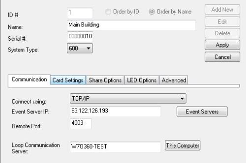
Create a brief, meaningful Loop Name (you might want to include the Cluster ID for traceability – example: the name “Main Blg (01)” indicates it is cluster 1 at the main building.)
-
Set System Type to “600”. This supports both 600 and 635 models.
-
Set Connection Type to “TCP/IP”.
-
Enter the Event Server IP address (of the PC running the GCS Event Service)
-
The Remote Port should be “4003”
-
Enter the computer name of the Communication Server (i.e. the PC running the GCS Communication Service). Or click [ This Computer ] button if you are on the communication server.
-
Click Apply to save settings.
Loop/Cluster Programming screen

Other Options
-
Edit button lets user change the properties of an existing Cluster.
-
Delete button deletes the existing Cluster. You must delete controller first.
-
Apply button saves all changes and updates the panels.
-
Cancel button cancels the changes and exists edit mode.
See the Hardware Programming section of the SG User Guide for info about the remaining tabs.
Next Steps
Configure Serial Channels (DSI Sections)
These steps add a 635 Controller (and DSI board) to the loop/cluster.
PREREQUISITES
-
The core GCS Services must be running.
-
The controller should connected to the Event Server
-
The DSI Board(s) should be installed in the panel and configured correctly
-
You must have added the Loop/Cluster in System Galaxy.
-
To support Office Mode or Privacy Mode, you must be installing a 635-series CPU and 635-series DSI board.
-
Consider disabling any section that is not in use to minimize programming.
-
Open the Controller Properties screen: Configure > Hardware > 635 Controller
-
Select the Cluster name you just created in the previous step.
-
Click Add New to add a controller. If you are adding a DSI to an existing controller then select the name of the existing controller.
-
Enter the new CPU serial number (found on the CPU board).
-
Create a meaningful Name for the control panel (you may want to include the controller unit number for traceability – example: “First Floor (#01)” tells the operator or tech that the controller is unit 01 and serves the 1st floor. )
-
If this is a new controller …
-
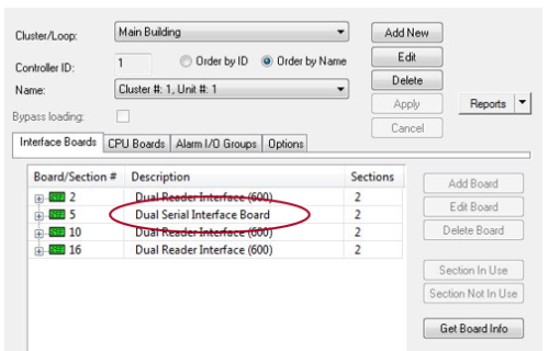
Click the Get Board Info button to open the Board Info screen and the list of boards.
-
Click Save in the Board Info screen, to automatically add all listed boards to this controller.
CAUTION: Clicking Save will delete preexisting boards and their system programming. Cancel to exit the Board Info screen without saving and preserve preexisting boards.
-
-
If this is an existing controller , click Add Board button to manually add a DSI to the existing panel. This preserves preexisting boards and hardware programming. Repeat this step as many times as needed to add .
-
Click Apply to save your controller and boards. Saving also loads the new data to the controller. You can also use the GCS Loader Utility to load programming.
Controller Programming screen

MAINTENANCE NOTE: If you replace an existing board in the panel by swapping it out, but otherwise all the same hardware is attached to the same port/section, then it is best to address the new board to match the existing/old Board ID in the system. This will preserve all the programming of the peripheral hardware.
Other Options
-
Section In Use button enables a section of a board.
-
Section Not In Use disables a section of a board.
-
Edit Board button lets user edit the properties of an existing board.
-
Delete Board button lets user delete a board from the controller.
NOTE: the system programming for peripheral hardware will also be removed from the system (readers, inputs, outputs, relays, etc.). The system may require you to delete peripheral hardware before you can delete the board.
Next Steps
Configure Serial Channels (DSI Sections)
These steps describe how to configure a DSI Serial Channel or board section and enable the readers.
PREREQUISITES
-
You must have added the DSI board(s) to the Controller Property screen before you can configure Serial Channels.
-
You must know which Reader numbers are installed on each DSI Section. Use your PIM/Reader Mapping table to help determine which readers to enable.
-
All readers on the same DSI Section must use the same card format.
-
You can mix AD400 and AD300 readers on the same DSI Section (network run) as long as they have unique Reader IDs and no duplicate PIMs.
-
If AD300 Readers are on the same section with AD400 readers, the AD400 PIM# cannot be the same as any AD300 Reader ID. Although the AD300 does not use a PIM, the system programmatically reserves the AD300 Reader number as a PIM #. So AD300 Reader #3 reserves PIM#3. None of the AD400 PIMS can use #3.
-
Open the Serial Channel screen : Configure > Hardware > Serial Channel
-
Select the appropriate Cluster/Loop Name
-
Select the appropriate Controller Name
-
Select the appropriate DSI Board & section number (e.g. Board 1; Sect 1).
-
Click Edit button.
-
Set the Channel Mode to either use ‘Wiegand’ or ‘ABA’, as appropriate to reader technology.
NOTE: setting this field to ‘Unused’ will disable the section programming.
-
Select the correct Network Type based on the hardware you installed …
-
AD-300 Only (Hardwired Network)
-
AD-400 Only (Wireless Network)
-
AD-400 & AD-300 (Mixed Network)
-
-
Configure the Reader Numbers as appropriate …
If a Reader number was skipped or omitted, or you installed less than16 readers, then you must uncheck the reader numbers that do not really exist on the network.
-
Enable (“check”) only the reader numbers that you physically installed on this DSI section.
-
Disable (“uncheck”) the readers that do not exist.
-
-
Click Apply to save changes.
Serial Channel Programming screen

Image is cropped to conserve space.
Next Steps